Commercial Ethernet vs Industrial Ethernet
- Kaitlyn Nelson
- Wire & Cable
- May 22, 2020
- 16677views
Commercial Ethernet vs Industrial Ethernet
What are the similarities and differences of Ethernet cable, and what does it mean for your next factory automation project? Also learn about 3 considerations you should have in mind when designing, planning, and implementing Industrial Ethernet networks.
While Ethernet technology has become widespread, the commercially available Ethernet technologies and category cables we use in our everyday work and personal lives are NOT the same as those being deployed across the world in Industrial settings to power the next generation of 21st Century factories.
Unfortunately, Commercial-grade Ethernet is too often mixed into industrial settings, causing far more detrimental impact to quality, productivity, uptime, and OPEX (Operational Expenditures) than can be recouped from the initial CAPEX (Capital Expenditure) cost savings of commercial cable and components.
By following a few key principles factory networking designers and installers can ensure the right Ethernet technologies for modern industry.
Commercial Ethernet was invented 40+ years ago as the de facto physical layer communication protocol for data transmission between local or wide-area computing devices.
With a standardized method of communication utilizing frames for sending information between devices, Commercial Ethernet’s broad popularity brought to bear high reliability, backward compatibility, and relatively low-cost digital communications that helped enable and revolutionize the Internet.
What Is Industrial Ethernet?
The popularity and effectiveness of Commercial Ethernet have led to mass migration, adaptation, and deployment into modern industrial environments in the past few decades.
As factory floors become increasingly efficient, intelligent, and automated each industrial plant became its own “internet of things”.
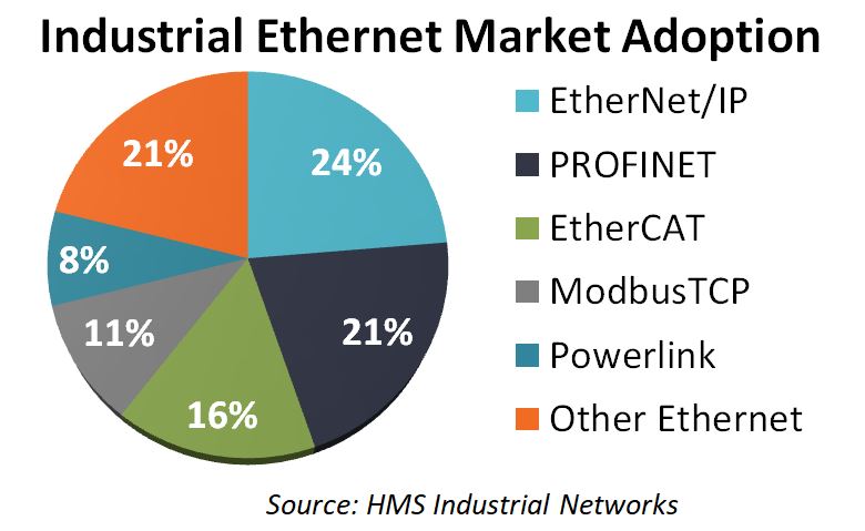
The term “Industrial Ethernet” refers to the utilization of Ethernet’s lower level layers (i.e. the Physical and Data Link layers) with higher-level industrial layers (e.g. the Application layer) found in modern Industrial Ethernet protocols, the most common of which are EtherNet/IP®, PROFINET®and EtherCAT® (see Industrial Ethernet Market Adoption Pie Chart).
While Commercial and Industrial Ethernet share some similarities, some important differences abound which are critical to the success of a modern industrial plant.
Ethernet shares some similarities, some important differences abound which are critical to the success of a modern industrial plant.
Commercial vs. Industrial Ethernet: What’s Similar?
Commercial Ethernet and Industrial Ethernet are built upon the same basic foundations and share similarities in a few respects:
- Both share some common communications characteristics such as frame sizes and signal levels
- Both use the same general physical layer and media (e.g. hardware) technologies, though as we’ll see later there can also be major differences depending upon the type of industrial application
- Both provide varying data transmission rates from 10 Mbps to 1 Gbps (and beyond), though 100 Mbps is a common speed for industrial applications. Commercial Ethernet is can be found at much faster transmission rates to handle the communication of high bandwidth uses such as movie streaming and video conference, while the amount of data bandwidth needed for sending automation information in a factory is much lower.
- Both use various “categories” of Ethernet cable (e.g. Cat5, Cat 5e, Cat6, Cat6a, Cat7.) depending upon the maximum transmission speed, bandwidth, and other network characteristics.
Commercial vs. Industrial Ethernet: What are the Differences and Why?
The major differences between Commercial and Industrial Ethernet come down to application requirements and operating conditions.
Commercial Ethernet is intended for enterprise networking applications such as office buildings and data centers where the typical environment is indoors, temperature-controlled, clean, electrically quiet, stable, and protected.
Industrial Ethernet, on the other hand, is an altogether different situation from two key aspects: the fundamental demands and purpose of an Industrial Ethernet situation, and next the environmental factors that can exist in an industrial setting.
First, Industrial Ethernet is used for the mission-critical purposes of maintaining production uptime (and avoiding costly line-down situations), maintaining quality, (and preventing costly waste and rework), and providing a critical control functionality of a modern, networked factory (and its associated automated equipment, instrumentation, and other systems).
Any loss of reliable communications signals can mean a direct and costly impact on an enterprise’s bottom line, and in worse-case situations even result in an unsafe work environment for employees.
Secondly, industrial settings can bring forth many environmental situations that can negatively impact an Ethernet network’s performance.
As we will see shortly, the effects of physical and electrical environmental factors are one of the most critical differences between Commercial and Industrial Ethernet networks and their associated hardware.
As a result, there are 3 practical considerations when designing, planning, and implementing Industrial Ethernet networks above and beyond Commercial Ethernet applications.

3 Considerations when Designing, Planning, and Implementing Industrial Ethernet Networks
Practical Consideration 1: Industrial Ethernet Signal Transmission, Determinism, and Protocols
Commercial Ethernet communications are not structured to be “real-time”. As information packets are sent back and forth in a Commercial Ethernet network issues can arise such as packet collisions or otherwise lost packets of data. When this is detected, the Ethernet transmission stops and is re-sent after a small time delay.
What all of this means is that the time required for a packet of information to reach its intended destination cannot be determined ahead of time, or in other words, is not “deterministic”.

This non-deterministic nature of Commercial Ethernet networks (and its resultant slight communications delays) may be fine for enterprise and other applications such as most data center and office business settings but can be entirely unacceptable in industrial applications where robots, control systems, and other automated equipment depend upon receiving information exactly at the right location, at the right time.
Any loss or delay of data between networked industrial equipment can result in flaws in the production flow as well as a loss of efficiency and quality control.
Industrial applications require the determinism of Industrial Ethernet networks, and each company will need to evaluate their individual needs and determine the optimal Industrial Ethernet protocol solution for their organization and situation.
Once the Industrial Ethernet protocol is determined, the selection of the appropriate Industrial Ethernet cable for EtherNet/IP®, PROFINET®, and EtherCAT® applications can then proceed forward.
Practical Consideration 2: Physical Environmental Factors
Industrial environments present a wide range of potential factors that can impact Industrial Ethernet communications performance.
As Industrial Ethernet cabling is routed through densely packed machinery and industrial processes in a plant it can be exposed to a wide range of physical, temperature, chemical, and other harmful effects.
While the catastrophic failure of cabling and connectors is always possible, it is the dropped or damaged Ethernet data packets (data frames) that are most often the cause of detrimental communications performance and ultimately harmful impacts to productivity, quality, and uptime.

To provide a common framework for evaluating physical environmental factors related to Industrial Ethernet networks, various international standards such as TIA1005 and ISO 11801:3 as well as Industrial Ethernet protocol consortiums like the ODVA utilize what is commonly referred to as the M.I.C.E. requirements for Industrial Ethernet cabling systems.
- The “M” indicates the Mechanical environment – cables may be subject to severe physical-mechanical forces, such flexing to different degrees and frequencies, or being crushed (e.g. run over by a forklift).
- The “I” stands for Ingress, which brings attention to Ethernet connectors that need to be able to block the entrance of harmful liquids, dust, and gases from areas where they can cause damage.
- The “C” stands for Chemical or Climate-related impacts such as extremes in temperature, humidity, and the presence of harmful oils (e.g. machine tool coolants) and industrial chemicals (e.g. solvents).
- Lastly, the “E” in M.I.C.E. represents Electromagnetic effects which we will talk about in the next section.

The following are the most common practical considerations to address physical environmental factors in Industrial Ethernet settings:
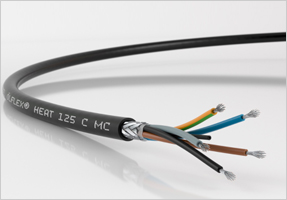
- Motion: Modern industrial settings are full of motion and movement, from robots to moving assembly lines and gantries, all of which require specialized Industrial Ethernet cabling to withstand these effects. These applications can lead to unique needs for different types of flexing cable capabilities. Many applications can utilize Industrial Ethernet cabling rated for “Stationary” applications, but increasingly factories have applications requiring “Flexible” cabling or even “Continuous Flex” rated Ethernet cable for the most rigorous, always-moving, high flexing cycle situations. Lastly, industrial applications with twisting machinery will require Ethernet cabling designed and tested for “Torsion” In general, manufacturers design and construct cabling with higher numbers of thinner copper conductors (e.g. high copper “strand count”), arrange the conductors in specific patterns and then use specialized jackets (such as Polyurethane) and shielding configurations all to optimize for the type of motion the cable will be subjected to.
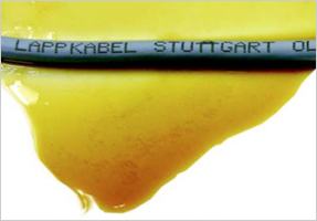
- Water, Oils & Chemicals: For general resistance to water and chemicals the use of widely available PVC-jacketed Industrial Ethernet cabling provides an effective economical solution for most industrial applications. PVC is highly moisture-resistant and suitable for wash-down applications, while also providing good general chemical resistance including many solvents. However, the presence of industrial oils (for cooling and lubrication) and cutting fluids require the use of either Polyurethane (PUR) or Thermoplastic Elastomer (TPE) Industrial Ethernet cabling since these two materials avoid the degradation effects of oil when exposed to PVC materials.

- Abrasion: Cables can be subjected to scratching, cutting, and friction when exposed to other moving pieces of equipment. The use of Polyurethane (PUR) or Thermoplastic Elastomer (TPE) jacketing materials instead of PVC provides additional protection to Industrial Ethernet signals in these situations. As one can see, the choice of an Industrial Ethernet cable’s jacket material has major fit-for-purpose implications. The accompanying table provides an overview of the appropriateness of the top 3 Industrial Ethernet cable jacket materials versus the most common physical “stressors” found in industrial environments.
PVC
(Polyvinyl Chloride)PUR
(Polyurethane)TPE
(Thermoplastic Elastomer)Heat Good to Excellent Excellent Outstanding Oil Fair Outstanding Outstanding Low Temp Flex Poor-Good Excellent Outstanding Weather Good to Excellent Excellent Outstanding Abrasion Fair-Good Excellent Excellent Flame Excellent Excellent Outstanding Water Good to Excellent Good to Excellent Excellent Acid Good to Excellent Excellent Excellent Alkali Good to Excellent Excellent Excellent Degreaser Solvents Poor-Fair Excellent Excellent - Zero Halogen, Low Smoke, and Flame Retardant Applications: For applications where a fire is a key concern for your environment, the selection of the appropriate Ethernet cable jacket is of paramount importance. Industrial Ethernet cables that are either Halogen-Free or Low-Smoke-Halogen-Free (LSZH) are constructed of specialized materials to not emit harmful halogen smoke when under fire, which can be extremely harmful to human beings. The most fire-stringent Ethernet cable is designed to meet Flame Retardant and Non-corrosive (FRNC) requirements which make them much less susceptible to burning at all to prevent flame spreading in fire situations. See the table below for comparisons.
Type Characteristics Halogen-Free No halogen materials which emit thick toxic and corrosive smoke Low Smoke, Zero Halogen (LSZH) No halogen materials and little smoke Flame Retardant and Noncorrosive (FRNC) No halogen materials, flame retardant
- Ruggedized Connection Points: The overall integrity of an Industrial Ethernet network is only as strong as its weakest link, which oftentimes can be at termination and connection points. As with other discrete network components, Industrial Ethernet Connectors must be selected appropriately for each individual application. RJ45 Industrial Ethernet plug connectors and their push-pull locking mechanism are the most widely established Ethernet connection technology and are available in many configurations including plastic and metallic housings. RJ45 connectors are typically rated to IP20, meaning no protection versus liquids. M12 circular plug connectors present an alternative connector technology that conforms to protection class IP67. Lastly, more ruggedized connector technologies conforming to IP68 (continuous immersion) are also available. These levels of Ingress Protection apply to stand-alone Ethernet connectors as well as Industrial Ethernet cordsets and patch cord assemblies. See the table below for a review of the common Ethernet connector Ingress Protection levels as defined by IEC60529.

| Protection vs Solids | Protection vs Liquids | |
|---|---|---|
| IP20 | Solid objects larger than 12.5mm | No protection |
| IP67 | Dust-tight | Protected against temporary immersion up to 1m |
| IP68 | Dust-tight | Protected against continuous Immersion |
Lastly, Industrial Ethernet switches can differ from their Commercial versions with more robust housings, mountings, and other physical features that are conducive to industrial environments.
Practical Consideration 3: Electromagnetic Environmental Factors
Today’s industrial plants are a veritable electromagnetic “ocean” inhabited by numerous generators of noise such as large motors, VFD (Variable Frequency) drives, arc welders, induction heaters, ovens, power lines and many more.
This electromagnetic ocean can drown out our meticulously constructed Industrial Ethernet networks with magnetic, RFI (Radio Frequency Interference), and electrostatic noise if network architects and installers aren’t careful.
All it takes is one bit of damage to an Ethernet communications packet and a frame error could cause the receiving device to reject the entire packet.
As previously mentioned, international standards providing best practices for Industrial Ethernet via the various “M.I.C.E.” framework where the “E” stands for Electromagnetic noise.
These best practices include the selection and installation of cables and connectors in higher noise industrial environments. For example, the ODVA provides guidance for Ethernet/IP networks with respect to different levels of electrostatic discharge, radiated RF, Conducted RF and magnetic fields. The following are a few practical considerations for Electromagnetic noise in Industrial Ethernet environments:
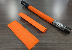
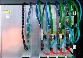
- Selecting the Proper Shielding for Cables: Industrial Ethernet cable is available in Unshielded Twisted Pair (UTP) and Shielded Twisted Pair (STP) configurations. While unshielded cable may be acceptable in some applications, the use of shielded cabling can reduce or nearly eliminate noise issues. A cable’s shield is a layer of conductive material between the copper conductors and the jacket that protects the communications signals from electromagnetic noise entering into the cable’s conductors. The shield absorbs and conducts this energy to ground diverting from negatively impacting the Ethernet signal. Shielded Industrial Ethernet cable is generally available with 2 types of shields, either Braided or Foil and Braided. Industrial Ethernet cable a with braided shield is constructed with a layer of fine wire mesh to form the shield. This braided wire mesh (see image) provides strength and flexibility as well as up to 95% electromagnetic coverage, particularly effective at lower frequency noise ranges. On the other hand, Industrial Ethernet cable with a foil and braided shield has 2 layers of shielding (see image), the aforementioned braided mesh shield, as well as a second foil shield. The foil shield is a thin film of solid metal that provides 100% electromagnetic coverage that is effective at higher frequency noise ranges. The combination of foil and braid shields provides the best shield coverage across the electromagnetic frequency spectrum. In extreme cases where foil and braid shielded cabling is not sufficient, other types of communications media such as fiber-optics should be considered.


- Using Proper Grounding Practices for Cable Shielding: The use of shielded Industrial Ethernet cable provides a very effective solution for electromagnetically “noisy” environments but their shields must be properly grounded to perform the shielding function appropriately. Refer to industry-accepted guidelines for cable grounding such as ODVA’s “Ethernet/IP Media Planning and Installation Manual” or IEEE-518-1982 “Guide for the Installation of Electrical Equipment to Minimize Electrical Noise Inputs to Controllers from External Sources” amongst others for detailed procedures. In general, the shield should only be grounded at a single point (the EtherNet/IP recommendation is at the switch end) in order to eliminate the possibility of ground loops, which occur when there is a potential difference between 2 ground points. This secondary current path and its resultant noise will impact the cable’s signal performance.
- Apply the Best Practices for Cable Routing during Design and Installation: In addition to the proper selection of shielded cable and good grounding practices, the proper design and routing of Industrial Ethernet cable within a factory environment are extremely critical for maximum performance. Again refer to industry-accepted guidelines for cable grounding such as the ODVA’s “Ethernet/IP Media Planning and Installation Manual” or IEEE-518-1982 “Guide for the Installation of Electrical Equipment to Minimize Electrical Noise Inputs to Controllers from External Sources” amongst others but here are a few examples of common best practices:
- Lengths of cable segments. In general, keep each cable run as short as possible. The longer distance a cable segment is the more susceptible it is to signal degradation and external noise effects.
- Excess cabling. If excess cable results from any specific network segment do not coil it up, which can lead to signal degradation, but rather cut and terminate it appropriately per manufacturer and installation guidelines.
- Manufacturer ratings. Always follow manufacturer ratings for critical attributes such as cable bend radius and maximum pull strength. These standards can be difficult to adhere to during a hectic project timeline with many individual installers but these ratings ensure the cable retains its integrity to communicate the Ethernet signals at maximum integrity.
- Crossing signal cables with power cables. If signal and power lines must cross make sure they cross at right angles to minimize the amount of cabling that is exposed and the resultant noise.
- Avoiding electromagnetic noise sources. Avoid routing Ethernet cabling next to high emitting sources. The ODVA for EtherNet/IP recommends a distance of at least 5ft from high voltage enclosures or RF/Microwave sources. Common sources include electric motors, VFD drives, power lines, arc welders, and induction furnaces.

- Metal conduit. If the cable is installed in metal conduit then each conduit section must be soundly electrically attached to adjacent sections for continuity purposes.
- Dynamic factory environments. Factories are always changing and moving. Be careful of intermittent or dynamic situations within a plant such as mobile equipment, modifications to layout, line expansions, and adding new pieces of equipment all of which could change the electromagnetic “profile” of the plant. These can be overlooked or be unknown during a network’s design phase.

Conclusion
As modern factories start to fulfill the promise of Smart Industry 4.0 and the IIoT (Industrial Internet of Things), their networking technologies must be up to the task of high performance and reliability over time in increasingly challenging industrial environments.
By understanding the basic foundations of Industrial Ethernet and keeping a few practical considerations in mind during design and installation related to physical environmental factors as well as a plant’s electromagnetic environment you can realize the benefits of a truly “Industrial grade” Ethernet network.

Related Posts


Categories
Recent Posts