Global VFD Solutions Exceeding Industry Standards
- Kassie Teagarden
- Wire & Cable
- Feb 7, 2020
- 4769views
Global VFD Solutions Exceeding Industry Standards
Original Content Written By: John Gavilanes, Director of Engineering at LAPP
LAPP leads the industrial cable industry by offering robust VFD cable (variable frequency drives) to meet needs for automotive and motor-driven equipment.
Variable Frequency Drives (VFDs) – also commonly referred to as Adjustable or Variable Speed Drives – improve the efficiency of motor-driven equipment and allow for accurate continuous control over a wide range of operating speeds.
The VFD market is continually expanding on an increasing scale to support the increasingly intelligent and sophisticated machines designed by engineers. To help ensure uninterrupted operations, cable performance has never been more in the spotlight.

Electrical phenomena known as cable charging current (CCC) and common mode current (CMC) can create troublesome issues with VFDs and can cause disruptions throughout an entire system.
LAPP offers a range of products comprised of both thermoplastic and thermoset insulation systems that provide solutions to help enhance VFD performance and offset these electrical issues.
Machinery using high performance VFD motors has been shipped with cables from overseas manufacturers to help present a “complete package”.
It is critical to ensure that these cables conform to NFPA codes and regulations so there are no compliance issues during the installation process. LAPP products comply with current NFPA 79 requirements and new revisions to be included in the 2021 edition.
For more details concerning the upcoming changes in 2021, see LAPP’s updated NFPA 79 Electrical Standard for Industrial Machinery whitepaper.

VFD Theory
Frequency is an electrical term describing power pulses of voltage and current over time. The standard frequency level in the United States is 60 hertz (Hz) or 60 power pulses per second.
These power pulses are called frequency cycles; there is one positive and one negative pulse of voltage in a single frequency cycle. Regional power companies provide the source power for all electrical operating equipment.
The source power may go through a factory’s transformer to either step up (increase) or step down (decrease) the voltage, but the frequency will remain constant at 60 hertz. There are four main components of a drive system: source power, the VFD, the cable, and the motor.
Ancillary components – resolver/encoder feedback devices, tachometers, sensors, and relays – may also be incorporated for increased performance.
Variable frequency drives have become increasingly prevalent in industrial applications where frequency is used to finely adjust the speed of a motor. The primary role of the drive is to send the power pulses that control the motor’s start-up, operating speed, and stopping functions.
Increasing the frequency of the drive will increase the motor’s speed; conversely, decreasing the frequency will cause the motor to slow down. The VFD performs three steps in order to adjust the speed of the motor (see illustration below):
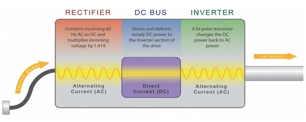
Alternating current (AC) is the primary source of electrical power in the USA. The VFD’s first job is to convert the source power from alternating current (AC) to direct current (DC).
During conversion, the voltage of the source power is multiplied by a factor of 1.414, while the frequency remains at 60 hertz.
For example, an incoming source power of 460 volts ACwill be converted to 650 volts DC. This process is necessary before the power can be changed back to AC so that the variable frequency can be used for VFD applications.
The second part of the drive is the DC bus, an electronic component that stores energy. The DC bus acts as a large storage battery that supplies DC power to the third part of the drive, the inverter.
The inverter converts DC back to AC, allowing for the inverter to control the frequency of the current sent to the motor, which then affects its operating speed.
This is the advantage of using a variable frequency drive – the pulse width modulation (PWM) frequency is approximately 20,000 hertz and offers finer control by only varying a few cycles of current at a time.
However, at the power source frequency of 60 hertz affecting a few cycles only offers a limited degree of change and does not allow for control as precise as with PWM.
The VFD outputs a flow of AC power pulses at a certain frequency which provides or maintains the desired speed of a running motor via power supply cables.
It is extremely important to select the appropriate cables for an application to avoid any disruption in power pulses, which would result in a drop in precision control of the motor and potential downtime.
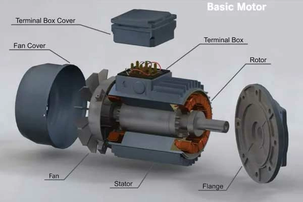
A basic motor consists of a rotor, which physically rotates, and the stator, which remains stationary. When power is applied to the stator, a rotating electromagnetic field is created, which causes the rotor to turn. The stator is constructed by winding insulated wire a specific number of times in a defined configuration.
This area is the defenseless part of the motor; the wire insulation is extremely thin and can get nicked during the winding process. These nicks in the wire become bare spots of exposed conductor from which high voltage spikes may arc to the unit’s housing, leading to motor failure.
What Happens
The conversion of power from AC to DC and then back to AC is not a clean transition. Unfortunately, power distortions created during conversion are sent back through the source power system, resulting in unwanted additional voltage and current.
This higher flow of power causes the motor to run faster, causing overheating and high-voltage stress. In applications using sensitive clock or timing functions, critical electronic equipment can become confused. The motor and power supply cables that carry these electrical distortions are not immune to damage.
As mentioned previously, electrical phenomena occurring with these VFD cables known as cable charging, or common mode currents, can cause havoc with the motor and other components comprising the VFD system itself.
Non-linear power is defined as a change in voltage without the same change in current.
Under ideal conditions, the motor anticipates a power pulse and regulates the correct amount of current provided so the increase in speed can be sustained.
However, with non¬linear power the current does not properly support the motor’s requirements, and the distorted current can create high-voltage stress and cause excessive heat.
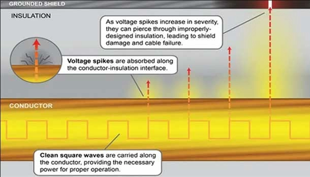
A spike is an exceptionally quick increase in voltage that occurs for a very short period of time. During inversion, the voltage must rise from zero to 650 volts, then back to zero approximately 20,000 times per second.
During this process, the nominal voltage can overshoot from 650 volts to 2,000 volts, or more. A longer length of power supply cable will experience greater and more intense voltage spikes than a shorter cable length.
Even though voltage spikes last for only millionths of a second, permanent damage can result with improperly-designed cables.
During initial motor start-up an inrush of current occurs, causing the motor and power supply cable to act as a large capacitor which must be charged up to its normal operating level. When the motor is first energized there can be a draw of up to six times its full load power requirements.
It is critical to remember that the cable installed must be of sufficient AWG (mm2) size to adequately support system ampacity requirements and to avoid any significant voltage drop.
The Problem With Cable
Cable plays a very important, and for the most part a “widely overlooked and often ignored role” in overall VFD system operation performance.
Expensive VFD’s, motors, other associated equipment, will not provide optimum performance unless the correctly designed VFD cable is used during installation.
It is very important that a cable intended for use with VFD’s has: 1) the correct conductor symmetry, 2) high quality insulation & jacket raw materials, 3) a ground conductor insulated with the same materials as the power conductors, and 4) an overall high coverage braid shield incorporated into its design.
In addition, the factors of correct installation along with consistent termination practices and proper shield grounding are critical to performance.
Without qualified personnel and following these proper protocols, the VFD cable will do little to maximize system performance – in short, a VFD cable is only as good as its installation. Additionally, correctly designed and shielded VFD Cables will help reduce:
- Electrical safety issues
- Drive trips
- Control Panel and communication trips
- Electrical interference (EMI)
- VFD, PLC, and Motor failures
- Wasted energy
- Decreased prodution efficiency
- Increased factory downtime
- Cable failure
VFD drives have a self-diagnosis program enabling easy detection of a shorted motor. A voltage spike lasts only a few millionths of a second and the equipment will just drop off line.
When a cable’s insulation is punctured from a voltage spike, the current travels into the braid shield. This creates an extreme amount of heat and causes the braid to burn until a large enough hole has been created, at which point the cable insulation heals itself.
This process will keep repeating at different locations along the cable length until total failure occurs. There are many methods of diminishing unwanted electrical conditions in the components of a VFD system.
In order to protect cables from power distortions during the process of rectification, the 2020 National Electrical Code requires that the size of source power conductors is 125% of the full load current of the drive.
Changing the pulse rate or switching the inverter to a slower frequency can eliminate some harmonics
Filters, reactors, and isolation transformers can be added to the drive to clean up harmonics, but the tradeoff could potentially result in additional voltage drop from the power supply.
Because VFD motors are double-insulated, the likelihood of nicks in the insulation are greatly minimized.
After utilizing all of these methodologies and protocols, the cable often remains the most vulnerable component in the VFD system.
If the power supply cable is manufactured to prevent failure due to power distortions, then the system as a whole is equipped to handle the type of power that a VFD generates.
Cable Charging and Common Mode Current
For VFD’s there is the likely occurrence of certain electrical phenomena that cables will inherently experience in these systems; they are referred to as cable changing current, and common mode current.
These issues are generally associated with VFDs that are 480Vac or greater, and 5 HP or smaller.
To further explain, when the IGBT (Insulated Gate Bipolar Transistor) of the VFD switches over to DC bus voltage, a “surge” in current known as “cable charging current” travels down the cable.
Cable charging current can follow pathways from either phase to phase conductor or phase to ground conductor, or the cable shield.
The cable charging current that returns back on the grounding conductor or cable shield is referred to as the Common Mode Current. Basically, for VFD systems lower common mode current is more desirable as this reduces the probability of performance issues and other potential problems.
Outside of some common sense things like overheating due to dirty filters etc., the occurrence of common mode current is the number one problem with VFD installations.
It is the main culprit behind motor problems at manufacturing facilities - creating mystery downtime with faulty equipment and/or readings.
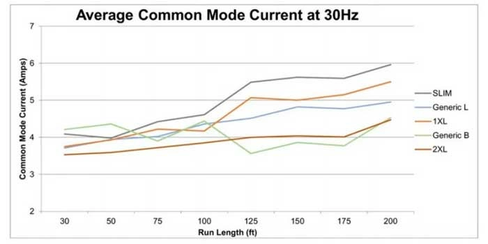
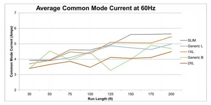
Note: These two graphs are based on actual performance data of the cable lengths shown. This evaluation was completed by an industry-experienced VFD drive system & installation specialist. Testing was performed under the same conditions commonly seen in real-world industrial applications.
LAPP's Insulation Material: XLPE (Plus)
For end use applications requiring the optimum in precision control such as those involving servo motors or encoders, LAPP ÖLFLEX® VFD cables with XLPE (plus) insulation ensures trouble free performance.
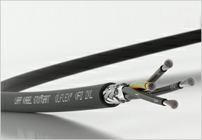
Both the LAPP ÖLFLEX® VFD 2XL and 1XL VFD cables are unique product innovations of reduced diameter design that offer easier handling, space savings in trays, and cables that are lighter in weight.
ÖLFLEX® VFD 2XL and 1XL products provide reduced overall diameter cable solutions exclusive to LAPP and not available from any other cable manufacturer worldwide!
ÖLFLEX® VFD 2XL meets all requirements for 2000 volt RHW-2 at standard 600 volt insulation thickness; ÖLFLEX® VFD 1XL meets all requirements of 600 Volt XHHW-2 while utilizing 30% less insulation thickness!
These innovations were the results of the tireless efforts of LAPP’s widely experienced wire and cable Engineers, extensive compound research and development, and our state of the art UL/CSA test laboratory.
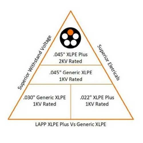
For VFD cables, the insulation materials used are very critical. Use of the XLPE (plus) insulation ensures minimal Common Mode Current along the various cable lengths.
With VFD’s, certain cable constructions can cause excessive charging currents and can interfere with proper application performance, resulting in unnecessary drive tripping and/or system damage. VFD cables with XLPE (plus) insulation will clearly stand out in several ways.
Cable charging current will be minimized which results in superior performance. LAPP XLPE (plus) insulation ensures minimal common mode current along various cable lengths which results in superior performance.
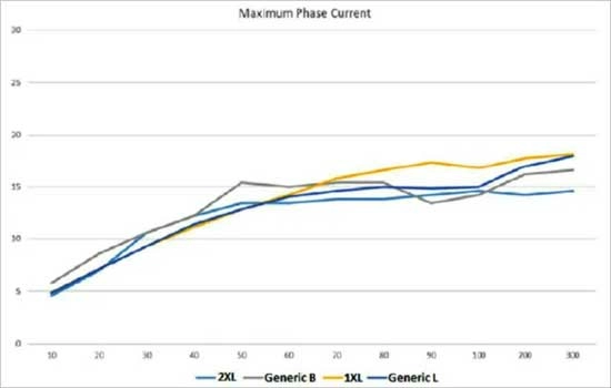
Concerning VFD’s, certain types of cable constructions can cause excessive charging currents which can hinder application performance, resulting in drive tripping and/or component damage.
To further In comparison to standard generic type XLPE cables, the XLPE (plus) insulation offers significant reduction as displayed in the following “Maximum Phase Current” graph to the left.
Note: This graph is based on actual testing data of each cable type indicated. All tests were performed on identical length samples and witnessed by LAPP at a global leading drive manufacturer’s testing facility. Testing was performed under the same conditions commonly seen in real-world industrial applications.
This issue is generally associated with VFDs which are 480V AC or greater, and 5 HP or smaller. When the IGBT (Insulated Gate Bipolar Transistor) of the VFD switches over to DC Bus voltage, a “surge” charging current is sent down the cable.
The cable charging current path can be from phase to phase conductor, or from phase to ground conductor or cable shield. The cable charging current that returns on the ground conductor or cable shield is often referred to as the Common Mode Current.
LAPP's Insulation Materials: LAPP Surge Guard
ÖLFLEX® VFD cable with Surge Guard insulation is unique among motor power supply cables.
Compared to larger-diameter VFD cables such as standard Generic Type B, THHN, or THWN conductors used in conduit, LAPP VFD cables with Surge Guard offer the perfect solution.
These cables are smaller in diameter and very flexible, which makes them ideal for use in areas where the allowable space is either too tight or restricted.
LAPP Surge Guard has a thermoplastic semi-conducting layer extruded over the conductor, followed by PVC insulation and a nylon covering.
Surge Guard insulation enables the cable to withstand the electrical irregularities that occur in VFDs under typical conditions of use: reflections, standing waves, and voltage spikes.
The key component of the LAPP Surge Guard is a semi conductive compound applied over the copper conductors. During periods of high voltage spikes, this semi-conductive coating disperses the electrical stress experienced by the conductor and prevents damage to the insulation.
This coating results in improved cable reliability, increased dielectric strength properties, and extended service life. In addition, tests performed under the ICEA T-24-380 standard inception and extinction levels improved significantly when semi-conductive compounds were used as part of the insulation system.
These compounds insure that LAPP Surge Guard insulation reliably helps maintain functional cable integrity under extreme operating conditions.
LAPP Surge Guard insulation is completed with an extruded second layer of PVC/nylon. This tandem component allows for operation under high temperatures and provides superior electrical mechanical strength.
In addition, the cable will maintain its superior crush and impact resistance to help support a UL TC-ER listing.
LAPP Global Stranding
The stranding configurations of specifically ÖLFLEX® VFD 2XL and ÖLFLEX® VFD SLIM cables offer several advantages.
ÖLFLEX® VFD cables automatically comply with both North American (UL, CSA) and Class 5 European (VDE) conductor stranding standards. The unique stranding provides a “one size fits all” global termination solution.
In addition, the resulting Circular Mil Area (CMA) is greater when compared to North American Wire Gauge (AWG) sizes.
Larger CMA means lower DC resistance, resulting in significantly lower voltage drop across identical cable lengths when compared to cables provided with the same AWG sizes.
The table below provides an AWG stranding comparability analysis between ÖLFLEX® VFD 2XL and a competitor sample. Also included are other LAPP VFD products ÖLFLEX® VFD SLIM, the innovative flexible reduced diameter ÖLFLEX® VFD 1 XL, and a generic bulkier industry standard type VFD cable.
| CABLE SAMPLE | ÖLFLEX® VFD 2XL & SLIM | ÖLFLEX® VFD 1XL | Generic VFD TYPES B & L |
|---|---|---|---|
| AWG CLASS | Class 5 | Class K | |
| AWG STRANDING | 1 AWG; 56/0.0117 | 12 AWG; 65/30 | |
| CIRCULAR MILL AREA | 7666 | 6500 | |
| DCR (X/1000 FT) | 1.36 | 1.73 | |
| CURRENT (AMPS) | 5 | 5 | |
| CALCULATION DCR X CURRENT | 1.36 x 5 | 1.73 x 5 | |
Both the ÖLFLEX® VFD 2XL and ÖLFLEX® VFD SLIM exhibit significantly less DC resistance than the Generic VFD Type B product. This results in lower voltage drop and higher current carrying capability which can be critical factors for certain VFD applications.
In general terms, more copper conductor area equates to lower DC resistance which results in less heat generated.
Superior LAPP Super EMI Shield
How a cable is designed and installed with respect to its shield will affect electrical performance parameters such as capacitance, inductance, and ground symmetry. These electrical attributes are essential to both the cable and overall performance of the VFD system as a whole.
As is the case, proper bonding, grounding, and termination are critical in order to achieve the full effectiveness of the LAPP Super EMI shield. Correct installation of the cable to the VFD and motor are essential for optimum performance and continued trouble free system operation.
It is very important to remember that while the cable can be viewed as the possible answer, it will not solve the problem if it has been improperly installed.
A VFD cable is truly only as good as the installation; if incorrect practices and protocols are used the cable itself will not provide the necessary solution.
All LAPP VFD cables are constructed with superior Super EMI shielding consisting of a tri-laminate foil tape in combination with a high-coverage tinned copper braid.
Cables with the Super EMI shield offer excellent transfer impedance characteristics as detailed in the graphs below:

Note: Transfer Impedance relates to a current on one surface of a shield to the voltage drop generated by this current on the opposite surface of the shield. Transfer impedance is used to determine shield effectiveness against both internal and external interference signals. Higher transfer impedance values are indicators of poor performance of the overall cable shield.
The shielding provides immunization against noise interference in two ways. Externally generated noise cannot enter from outside the cable to cause internal signal disruptions.
Any noise generated from within the cable itself is prevented from exiting, which would cause unintended disruption to nearby sensitive electronic equipment.
Shield effectiveness testing verifies the outstanding performance characteristics of the LAPP Super EMI shield in comparison to other types of generic cable shields types as depicted in the following graph.

Note: Screening attenuation is the measurement of decibel ratio between the internal and external signals of a device. In short, it is a ratio of electric or magnetic field strength before and after placement of a shield. For Screening Attenuation readings of lower dBs are indicators of poorer overall shield effectiveness performance.
A Quick and Innovative Termination Solution
LAPP offers a wide variety of metal cable glands, which fully complement the Super EMI shield system by quickly and easily providing a full 360° circumferential cable shield termination solution.
The full 360° is considered to be the best cable shield grounding termination method. The SKINTOP® MS SC is ideal for use with smaller AWG cables because they generally exhibit the most consistent cable concentricity and minimal eccentricity characteristics.
Larger AWG cables can be more challenging as they are inherently characterized by increased dimensions and corresponding fluctuations in core concentricity. In these instances, ensuring a full 360° shield termination can be a tedious and daunting task.
SKINTOP® MS BRUSH provides the ideal solution as this cable gland can conform to these cable irregularities and effortlessly ensure full shield termination.
SKINTOP® INOX SC and SKINTOP® HYGENIC SC are manufactured of robust stainless steel, which features a very smooth surface finish with no sharp protrusions, corners, or edges.
The smooth finish prevents the growth of bacteria and other micro-organisms from adhering to the surface making these glands the ultimate choice for the food and beverage industry. The durability of stainless steel offers high corrosive application suitability and superior resistance to wash down.
SKINTOP® cable glands are also referenced in Rockwell Automation’s Wiring and Grounding Guidelines for Pulse Width Modulated (PWM) AC Drives, further establishing creditably as the industry’s leading cable shield termination solution.
ÖLFLEX® VFD Jackets
The jackets used for ÖLFLEX® VFD cables consist of either innovative specially formulated thermoplastic polymer or elastomer (TPE) compounds that are environmentally friendly.
The attributes and durability of these jacket compounds allow for LAPP VFD cables to be used in applications for which a solution did not previously exist.
Superior flexibility ensures easier handling and routing during installation, especially when cable must be able to maneuver tight bend radius areas.
This one feature alone helps speed up the installation process, which in turn saves time and money. ÖLFLEX® VFD cables provide exceptional flame resistance as they all comply with the UL Vertical Tray and CSA FT4/IEEE 1202 flame tests.
In addition to compliance with these flame tests, all LAPP VFD cables maintain the associated regulatory cable listings permitting installation within the industrial infrastructure.
Exposure to harsh types of chemical environments will not present any issues because ÖLFLEX® VFD cable jackets comply with UL Oil Res I and II stringent test requirements.
ÖLFLEX® VFD jackets have exceptional resistance to crush and impact forces - these cables all maintain a UL TC-ER listing. Cables which are TC-ER listed have gone through the same mechanical crushing tests as required under UL 1569 (Metal Clad Cables).

LAPP cables exceed the crushing requirements specified under UL 1569 by at least 50%.
Compliance with the TC-ER listing guarantees that cable is not only suitable for installation in trays but can also extend beyond the industrial structure as permitted by NEC Article 336.
Because armoring is not required there is a huge savings in both the product cost and associated installation.
Where a wide variety of outdoor environmental conditions exists, ÖLFLEX® VFD cables can cover both the low end and high temperature range – rain or shine. The sunlight resistance attribute verifies that the cable is suitable for all weather conditions inherant in outdoor installations.
For applications that require performance in a wide operating temperature range, all ÖLFLEX® VFD cables would be the premier choice.
All of these cables pass the severe low temperature extremes of -40°C (cold bend) and -25°C (cold impact) testing, and can be used up to a maximum continuous operating temperatures of either 90°C or 105°C, respectively.
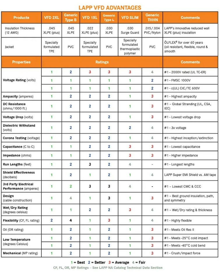
ÖLFLEX® VFD Advantage
LAPP cables are tested in accordance with applicable North American agency standards in our state-of-the-art test laboratory.
The LAPP North America Laboratory has been qualified by both UL under the Client Test Data Program (CTDP) and also by CSA under the Supervised Manufacturers Testing for Certification Program (SMTC).
We also have an internal 5V (validation) process which continuously confirms product integrity to uphold our continuing industry leading reputation for quality.
Cables are tested daily to verify that performance requirements are maintained and that overall product quality is being held to our higher LAPP standard.
LAPP VFD cables are comparable to the recommended cable designs specified for Allen-Bradley (Rockwell Automation) drives used in Type 1, 2, 3, 4, and 5 installations.
The table on the following page provides a general evaluation of the improved features of LAPP VFD cables in comparison to the commonly known VFD Generic Type products.
Regulatory Compliance or Consequence
Only the AHJ has the qualifications and experience to provide a determination concerning cable installation and end use application suitability.
The AHJ may reference industry standards such as local building codes, the National Electrical Code (NEC) or the Electrical Standard for Industrial Machinery (NFPA 79) for example, to help determine if an installation is in compliance with requirements.
It is also important to remember that interpretation of code requirements and subsequent adoption of any new regulations can differ between states, cities, or local municipalities.
No one wants to be held accountable concerning a hefty fine associated with an installation violation; nor do they want to be involved with an insurance claim or lawsuit.
The importance of the cable jacket print legend legibility and permanence cannot be overstated; it is a critical factor for any installation.
The print legend is the only verifiable means that the inspector has at their disposal to validate a cable’s associated listings, voltage, temperature ratings, and additional features (outdoor use, crush resistance, etc.) to further determine potential installation suitability.
All those involved with an installation, including project engineers, the electrical contractor, and the AHJ want to avoid mistakes and potential problems before, during, or after an installation.
Over 50 years in this business has allowed LAPP to build highly credible expertise -- making the cable selection process problem-free.
Because all of our VFD cables maintain the necessary listings and certifications for use in industrial infrastructure, customers can be confident that inspectors will not find any issues.
LAPP’s regulatory approvals are superior to those of the competitions’ VFD generic Type B and Type L cables to support a wide variety of applications, and can be used to service Canadian building installations.
Regulatory Codes
In an industrial environment, cables can be exposed to uncontrolled conditions including ambient temperature variations, hazardous atmospheres, coolants, lubricants, solvents, etc.
They can also be subject to potential physical damage. It becomes quite clear that a cable’s ability to maintain performance is a key factor during the selection process.
There may be areas throughout the installation where the cablemay be supported but at the same time not routed in the tray itself; under these conditions the tray cable must be rated for Exposed Run (TC-ER) use.
The cable’s ability to remain resilience under physical conditions of crush and impact forces, exposure to various chemicals, and operating temperature range extremes, while maintaining outdoor stability is the primary focus for code compliance in the industrial environment.

Conclusion
The ability to withstand the abuses of today’s harsh industrial world has become a critical factor in cable selection. The continued advancement of cable performance is due to changes in standard regulations and the increased interest in evaluation of characteristics mandated by the industrial marketplace.
As the market continues to evolve with technological innovations, the demand for outstanding environmental performance features of cables will only continue to grow.
LAPP continues to maintain a leading role in this area and remains committed to providing the best products available to the industries that are directly affected by these performance requirements.
Since its inception over 20 years ago, the LAPP Surge Guard insulation system has become a mainstay in the industry with historically proven reliability while maintaining unwavering OEM spec positioning.
The XLPE (plus) insulation is a first for the marketplace and has indeed “raised the bar” of cable innovation to the next level.
In their respective classifications, ÖLFLEX® VFD 1XL and 2XL products are reduced diameter cables that can support voltage ratings of 600V/1000V and 600V/1000V/2000V, respectively.
A smaller cable diameter results in less weight, provides for increased free space availability in the tray, and offers easier handling and routing attributes.
These LAPP design innovations have resolved issues that plagued installers for years, specifically the issue of conduit fill. The NEC mandates the maximum percentage of permitted area that cables can occupy within the inner conduit diameter space.
In short, larger diameter cables meant less fill space was available for installation, forcing contractors and installers either to increase the conduit size or run parallel conduits necessary to accommodate the same installation.
Now using these LAPP innovative smaller diameter cables, installers can avoid these scenarios. They now have the option to install more cables into the same sized conduit or reduce the number of conduits required.
These features and benefits allow for options enabling installations to be performed more quickly and easily, saving time and ultimately lowering the overall cost of the project.
Contact LAPP Tannehill today to discuss if ÖLFLEX® VFD Cables are the right solution for your application.
Related Posts


Categories
Recent Posts